|
The Audio 2 signal is an essential item for evaluating a transmitter. In
the old days, the distortion of a transmitter was about -30 dB, and the
distortion of the signal source was also sufficient if it was about -50
to 60 dB. However, when evaluating modern equipment, including homemade
equipment, some devices have a final output of -60 to 70 dB, so a signal
source with distortion < -80 dB is required. The original signal is
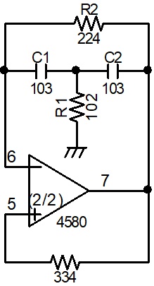
generated as a sine wave.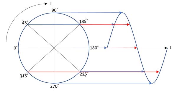 If a sine wave is expressed in amplitude and phase, it becomes a circle as shown in the figure above. The more perfect the circle is, the less distortion there is in the sine wave. Audio 2 signals are generally evaluated using two signals, 1KHz and 1.5KHz, and are composed of a C/R oscillator. A Wien bridge circuit is generally used as a circuit to oscillate a signal with little distortion in the C/R oscillator. 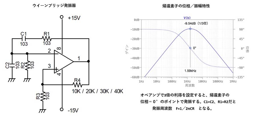  The key to a Wien bridge oscillator is to find a way to stably control the amplifier gain. It is necessary to set the feedback amount to a value that produces little distortion in the region where oscillation is stable. There is also a C/R oscillator circuit with little distortion called the "state variable CR oscillator" that is used in measuring equipment C/R oscillators.  COS/SIN OUT 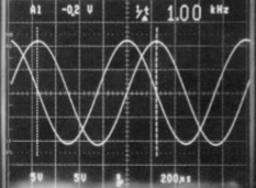 This circuit can obtain a signal with very little distortion (-80dB or less), but to obtain two signals (1KHz and 1.5KHz), a circuit twice as large as this would be required, which would make the circuit much more complicated and increase the number of parts. Another feature of this circuit is that it can also be extracted as a two-phase signal delayed by 90 degrees. Therefore, for some time now, when I need two audio signals, I have been using the following two-signal oscillator circuit, which is a modification of the Wien bridge. 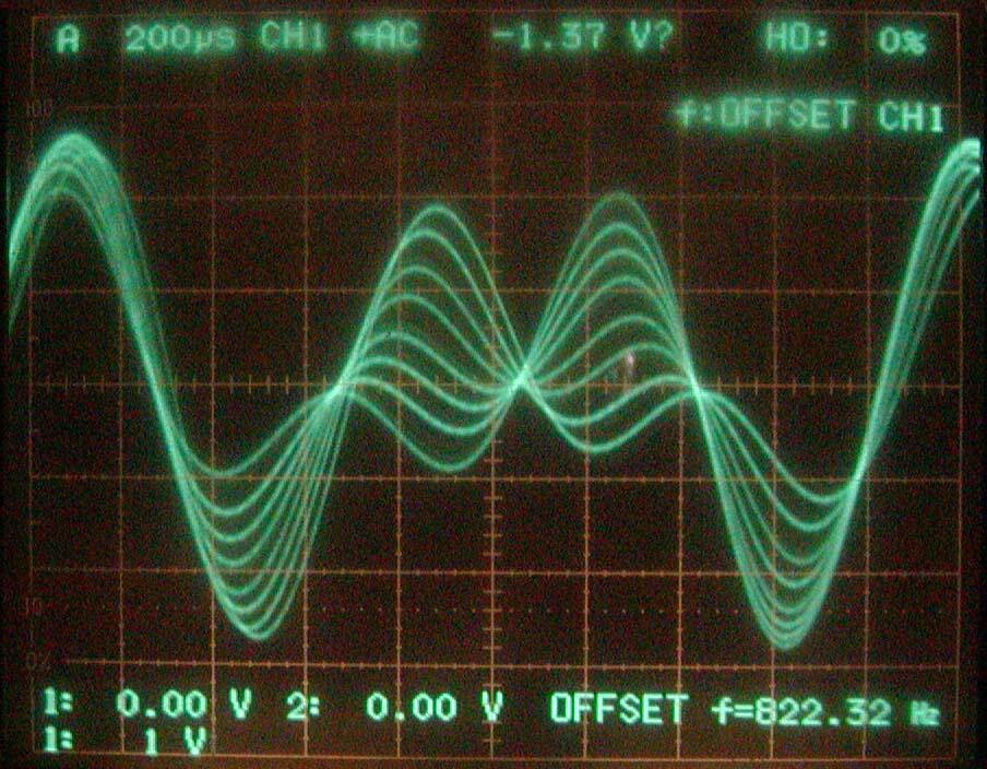  Output Waveform Output Distortion If you make it with the constants specified, adjust each semi-fixed VR (VR2/VR3) so that the output of each signal (1KHz/1.5KHz) is 6Vpp at each op-amp output ①/⑦. The optimal output amplitude changes depending on the Zener voltage of ZD1/ZD2. For the feedback AGC function, transistors (Q3/Q4) with excellent linearity are used as variable resistance between the collector and emitter. With general small signal transistors and FETs, distortion of -80dB or more cannot be obtained. After various experiments, the limit was -60 to -70dB. The thermistors (TH1/TH2) are used to stabilize the temperature environment and are sandwiched between the op-amp package and the printed circuit board. If you do not need them when using the actual device, you can delete them. Q1/Q2 are NPN type digital transistors, and applying a voltage of 5V or more to the input will stop each oscillation. Therefore, if you want to operate it as a two-signal circuit, turn both SWs OFF. In this state, the output of the 2 signals oscillates with a distortion signal of -85 dB or more. It may be overkill, but it is necessary for testing the -70 dB transmitter. 1KHz and 1.5KHz are generally used for the audio 2 signal, but if the accurate oscillation frequencies are 1.00KHz and 1.50KHz, for example, the 3rd distortion will appear at 2KHz, 5th distortion at 2.5KHz, and 7th distortion at 3KHz. On the other hand, the harmonics of 1KHz are 2KHz and 1.5KHz, and the positions of the 3rd distortion and 7th distortion will overlap with the positions of each harmonic, making it impossible to measure the distortion accurately. So, for example, if it is 950Hz and 1450Hz, the positions will not overlap. However, since the 2 signal oscillator is a CR oscillator, even if it is calculated at 1KHz and 1.5KHz, it will not oscillate exactly because it uses 5% error parts. It's useful to know this bit of trivia. 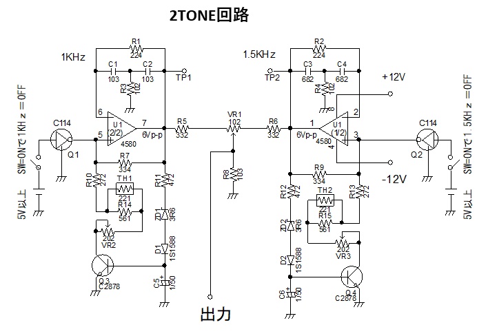
|